
How a fiido ebike controller beat my curiosity
Reversing a NC201 ebike controller board, with a shikra and ST-Link v2.
One random day my curiosity peaked about my e-bike’s motor controller. What does it does look like? Can you reprogram it?
First step was to remove the controller. It is apparently behind the seatpost that houses the battery. Removing the numpad was easy enough but the seatpost plastic sleeve was stuck real good. I had to hammer it out using a long metal post and hammer of course from the underside. After this, and prying open the seatpost clamps, it slid out easily. I marked the wire terminals with marker so reconnecting later will be a breeze.
First step was to remove the controller.
It is apparently behind the seatpost that houses the battery. Removing the numpad was easy enough but the seatpost plastic sleeve was stuck real good. I had to hammer it out using a long metal post and hammer of course from the underside. After this, and prying open the seatpost clamps, it slid out easily. I marked the wire terminals with marker so reconnecting later will be a breeze.
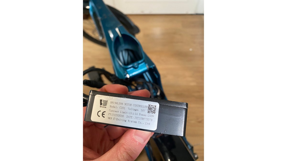
After liberating the controller and inspecting it I was happily suprised by its rugged and thermal designs. Its model is nc201 and its electrical board is called MS-EDS FZZ48VV350W. This name suggests the manufacturer makes one board for both its 36V/48V and 250W/350W controllers. It is also using a very common stm32g0x chip, however i misread the chipname as stm32c0x. This will bite me later! and has breakouts for uart and, more importantly, SWD. These are very promising signs for reversing the firmware!
Dumping the firmware
My first attempt at dumping the flash involved trying a “Shikra”, and older ftdi debugging board. It does not natively support SWD which is the protocol used to inspect flash on these stm chips. The Shikra is also abandonware. It took some time to find information about basic things like its pinout. After connecting its scl so and GND pins to the nc201 board ( self powered ), and using OCD to try to connect it turns out that, this path, it is fruitless.
So I asked a friend for a proper swd debugger: ST-Link v2. He gratefully lended it to me. Now i can follow this second path!
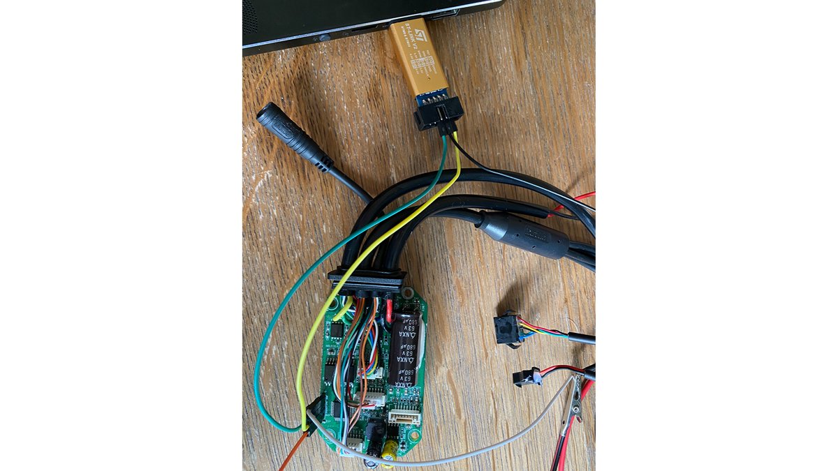
After hooking everything up and triple checking correct connections ( miswiring happens! xd ) i tried to connect using ./openocd -f interface/stlink-hla.cfg -f target/stm32c0x.cfg. At this time I still had the wrong chip in mind to target. Needless to say the debugger was unable to connect
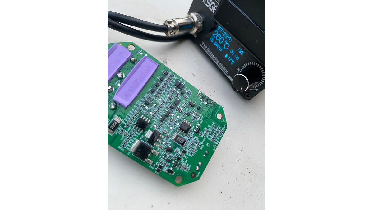
Coming back to it after a break, and inspecting the board more carefully, i noticed that 1. the ground pinout pin was loose, oh sweet instability! Next i cleaned leftover solder flux off the chip’s top and i discovered it is actually a stm32g0x chip, lol.
After fixing these problems and one ./openocd -f interface/stlink-hla.cfg -f target/stm32g0x.cf (notice the updated target name) the debugger connected with the chip, woohoo!
Now it’s time to investigate the flash info: in another terminal connect by executing telnet localhost 4444, then use flash info 0
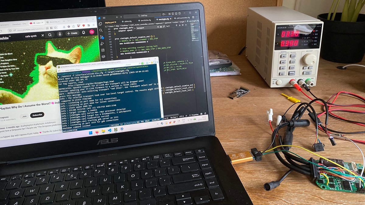
Unfortunately, this is where the adventure end: The flash memory is protected with RDP level 1. This means the flash and ram cannot be read out at all. Alas! Still, it was a fun small side track to follow :) I hope you dear reader have enjoyed it as much as i have